
Fittings made and measured at our own works
Our 2 lakh sq.ft works runs 71 machines, from cutting and forming (hydraulic presses up to 1200 tons) to welding, heat treatment, machining, finishing and marking. Our teams measure and test with the instruments and gauges on our List of Calibration.
From pipe rack to packed crate
The line a fitting runs at our Vasai (E) works: 13 stations in shop order. Scroll to run it, or drag the crane crab along its runway.
- Stations
- Phases
- Images
Serving every station: Material Handling 09 · Utilities 03
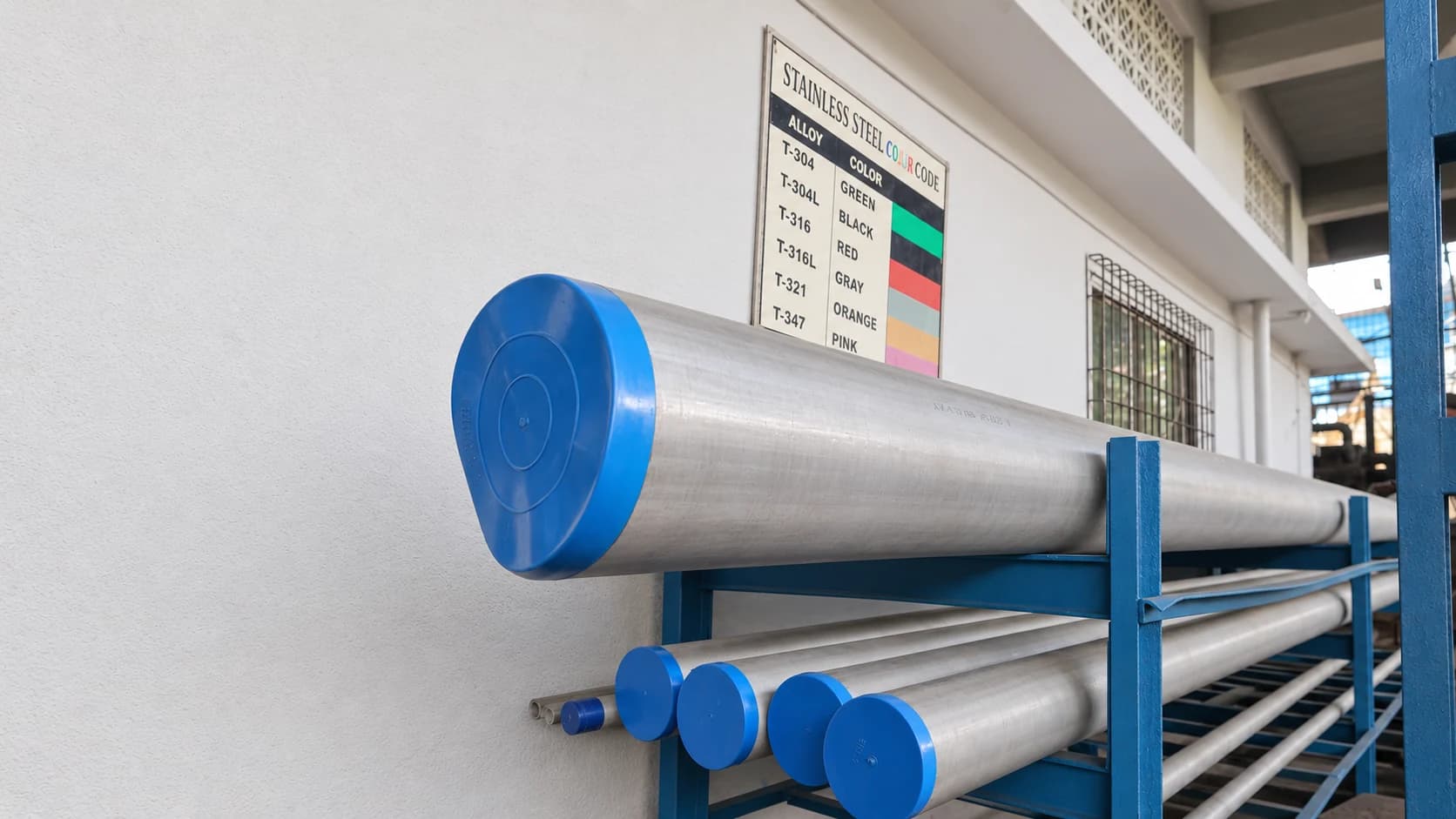
Fig. 01.1 — Stainless pipe racked under the grade colour-code chart 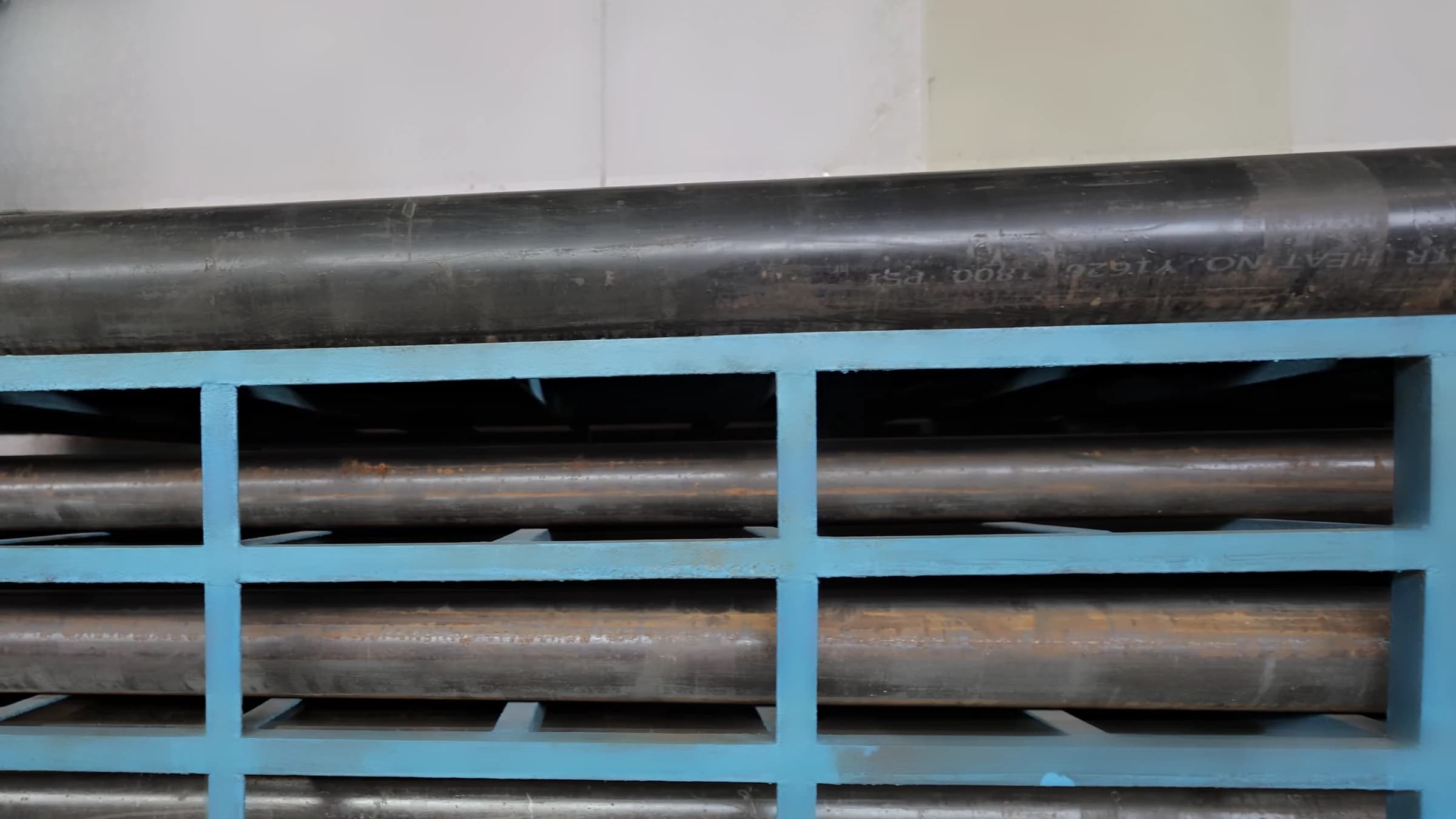
Material in
Station 1 of 13: Raw-material store
Carbon and stainless steel pipe is held on steel racks in our raw-material store: stainless lengths end-capped beside a colour-code chart for the grades, carbon steel carrying the mill's heat number.
OutRacked pipe
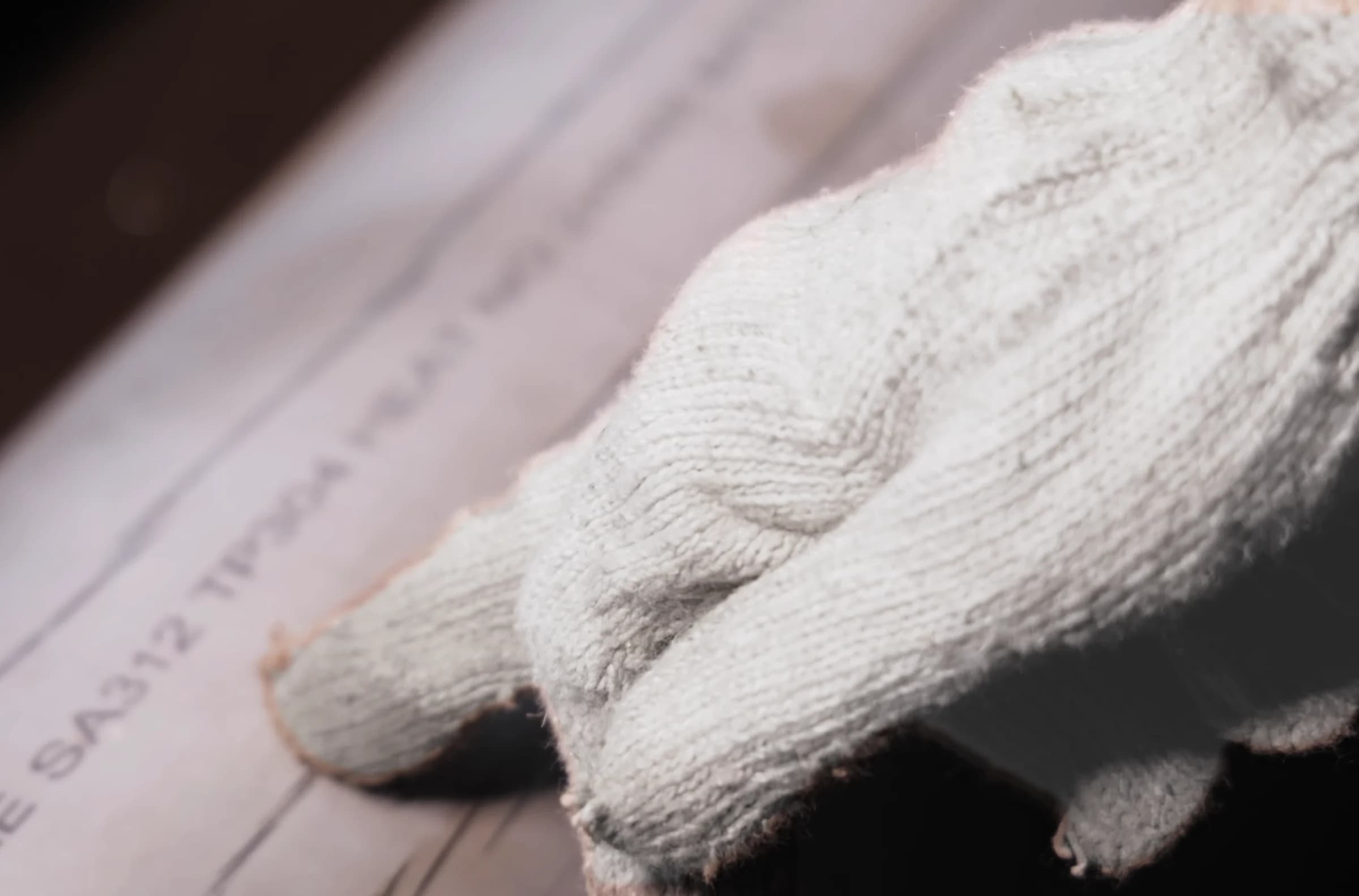
Fig. 02.1 — Mill marking read on incoming stainless pipe Checked before it is cut
Station 2 of 13: Incoming inspection
Incoming pipe is checked against its mill marking, here ASME SA312 TP304, and measured with vernier calipers and a measuring tape before it is cut.
OutVerified pipe
- Sr. 01–10Vernier Caliper (incl. one digital)×10
- Sr. 18–19Measuring Tape×2
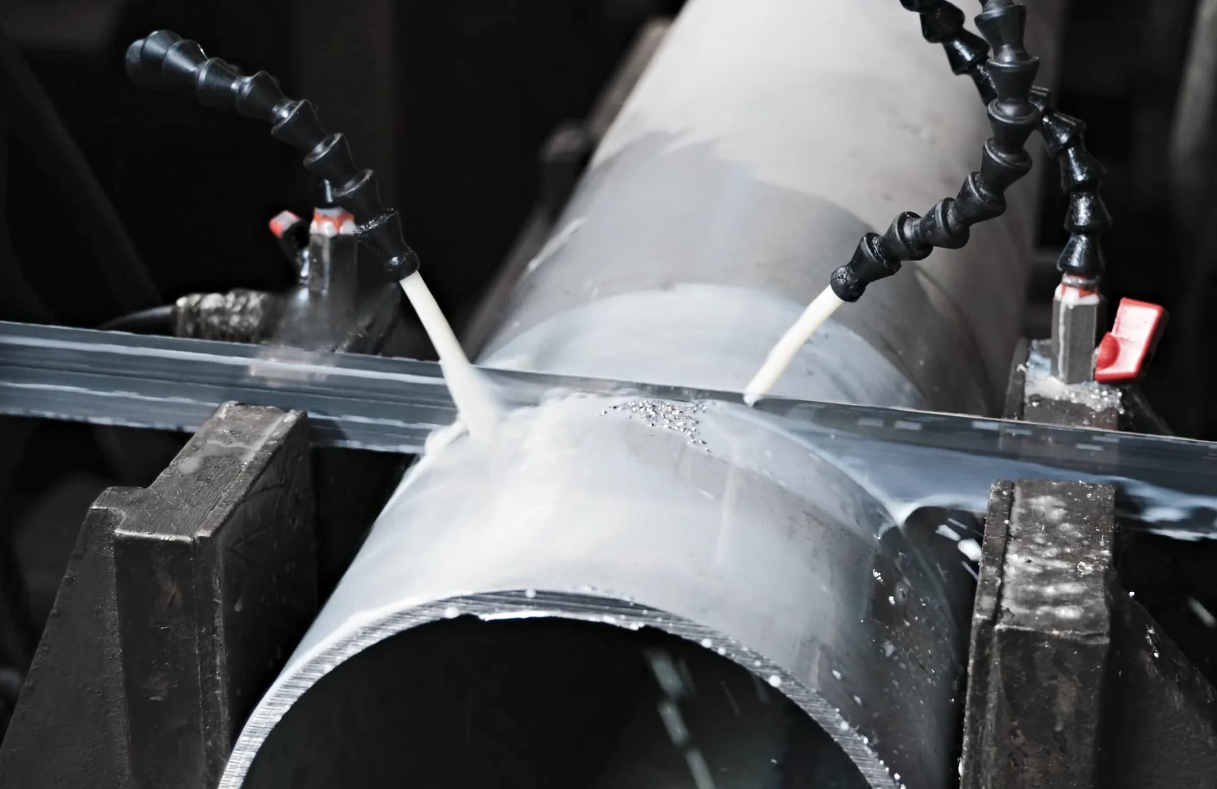
Fig. 03.1 — Band saw cutting stainless pipe under coolant 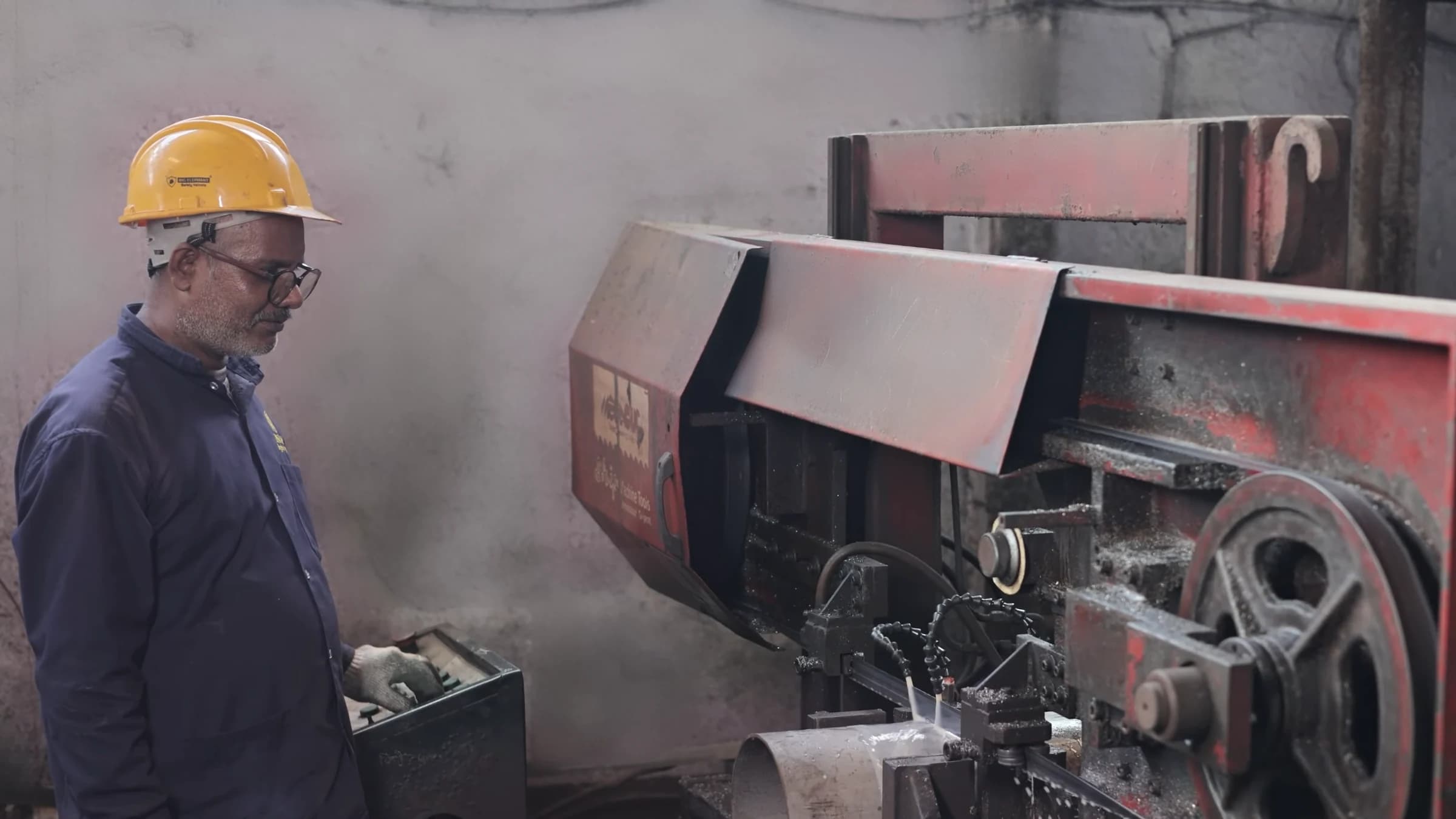
Cut to length
Station 3 of 13: Cutting
Pipe is cut to length on our band saws under jets of coolant. We also run air plasma units rated for 35 mm and gas cutting assemblies.
OutCut lengths
Band saws × 5- BS1–BS5Band Saw Machine×5
- AP1–AP2Air Plasma Unit — 35mm Thickness Capacity×2
- GC1–GC2Gas Cutting Assembly×2
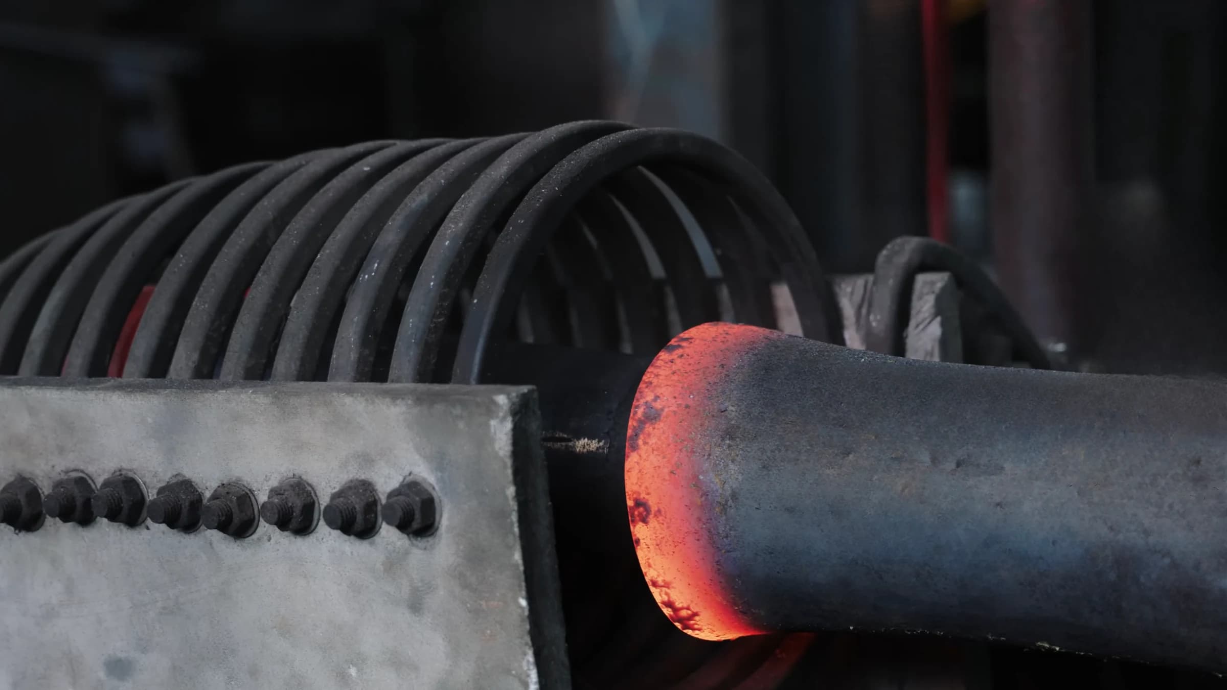
Fig. 04.1 — Mandrel machine HB1: the pipe end leaving the induction coil 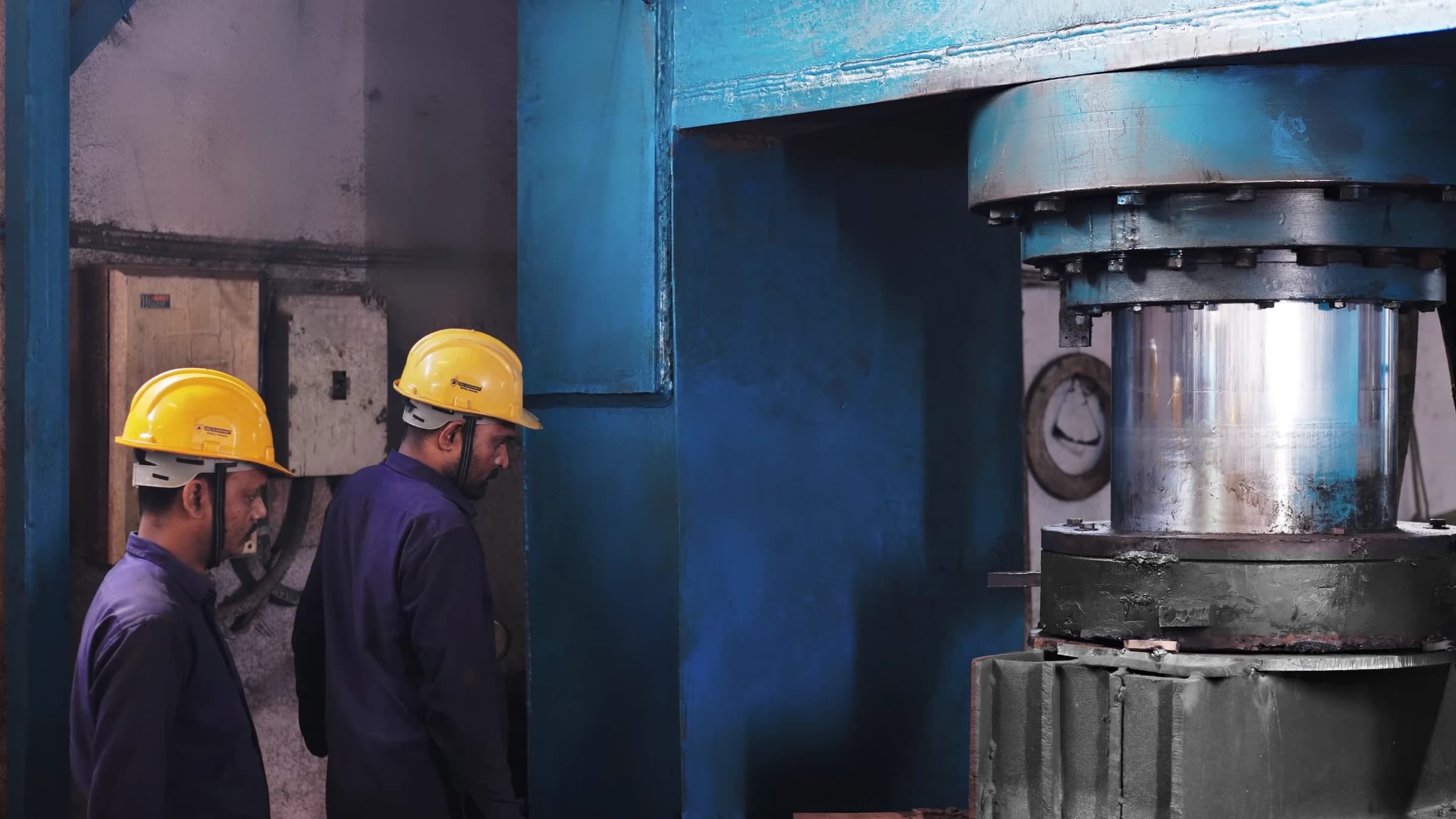
Hot and cold forming
Station 4 of 13: Forming
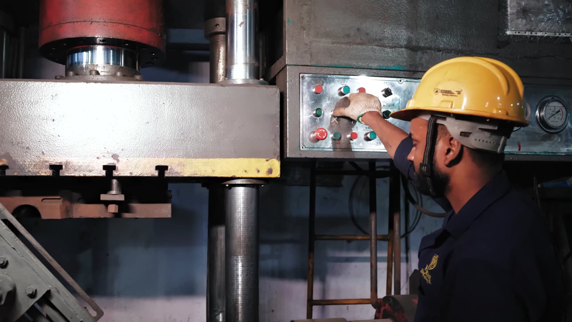
Elbows are hot-formed on our mandrel machine, the pipe heated red-hot in its induction coil, or bent cold. Tees are formed in dies on hydraulic presses from 200 to 1200 tons.
OutFormed elbows & tees
Elbows 4″ × S.40 → 18″ × 20 mm thkPresses 200 → 1200 T- HB1Mandrel Machine (Elbow Range: 4″ × S.40 to 18″ × 20mm thk)×1
- HP1–HP5Hydraulic Press — 200 to 1200 Tons×5
- CB1Cold Bending Machine×1
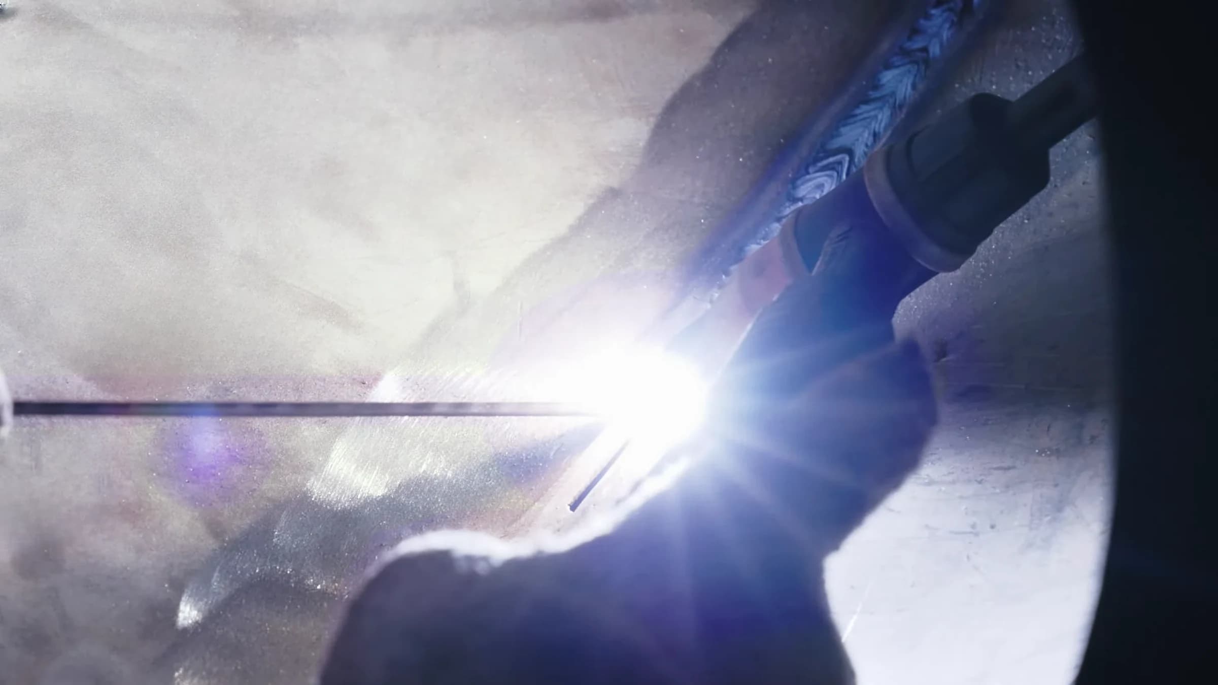
Fig. 05.1 — TIG arc and filler rod on a stainless fitting 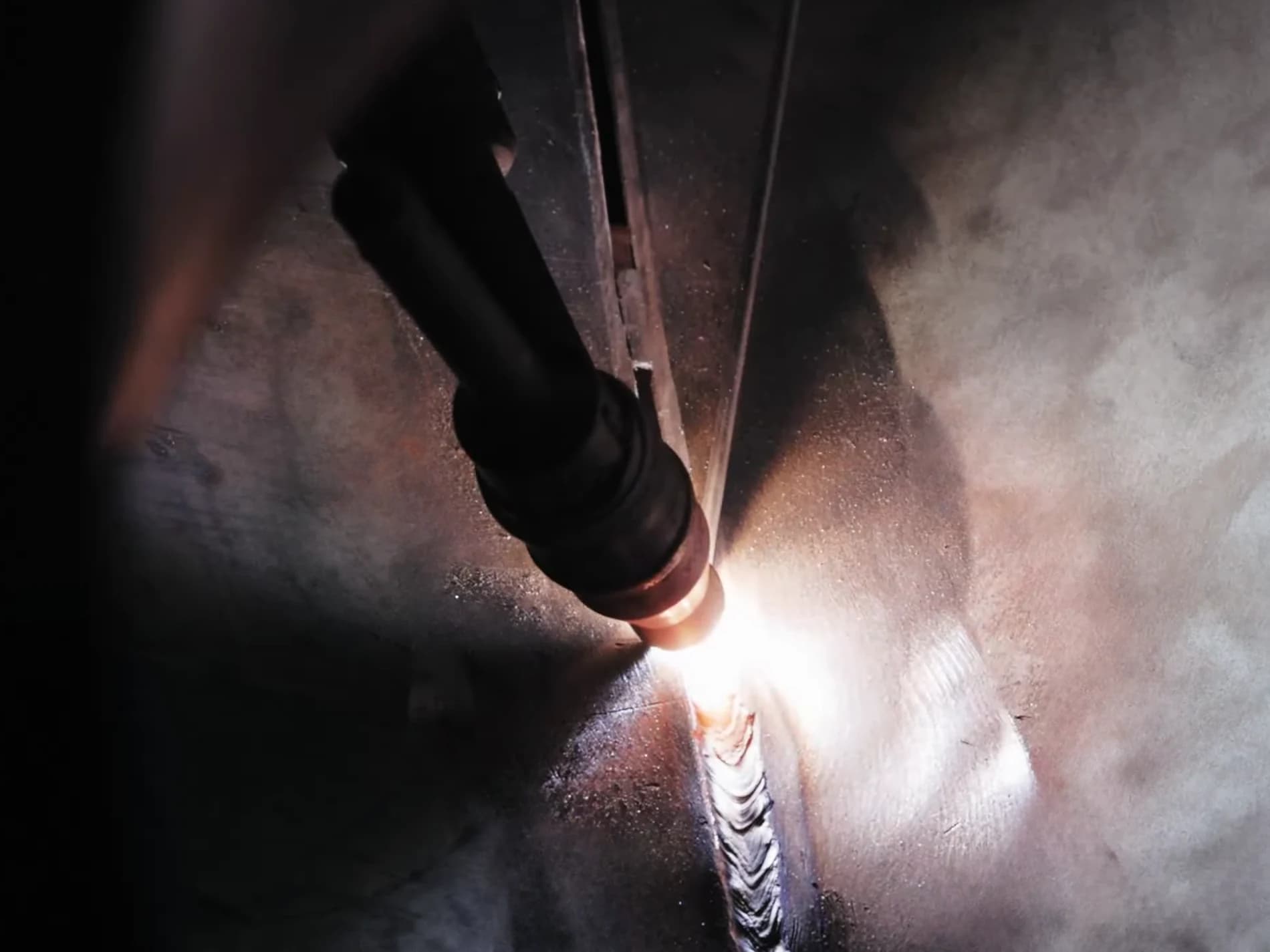
TIG welding
Station 5 of 13: Welding
Seams are TIG-welded by hand on our argon welding machines, 4 inverter-based sets rated 400 amps, the welder feeding filler rod into the arc.
OutWelded fittings
4 × 400 A · inverter base- WM1–WM4Argon Welding Machine (Inverter Base, 400 Amps)×4
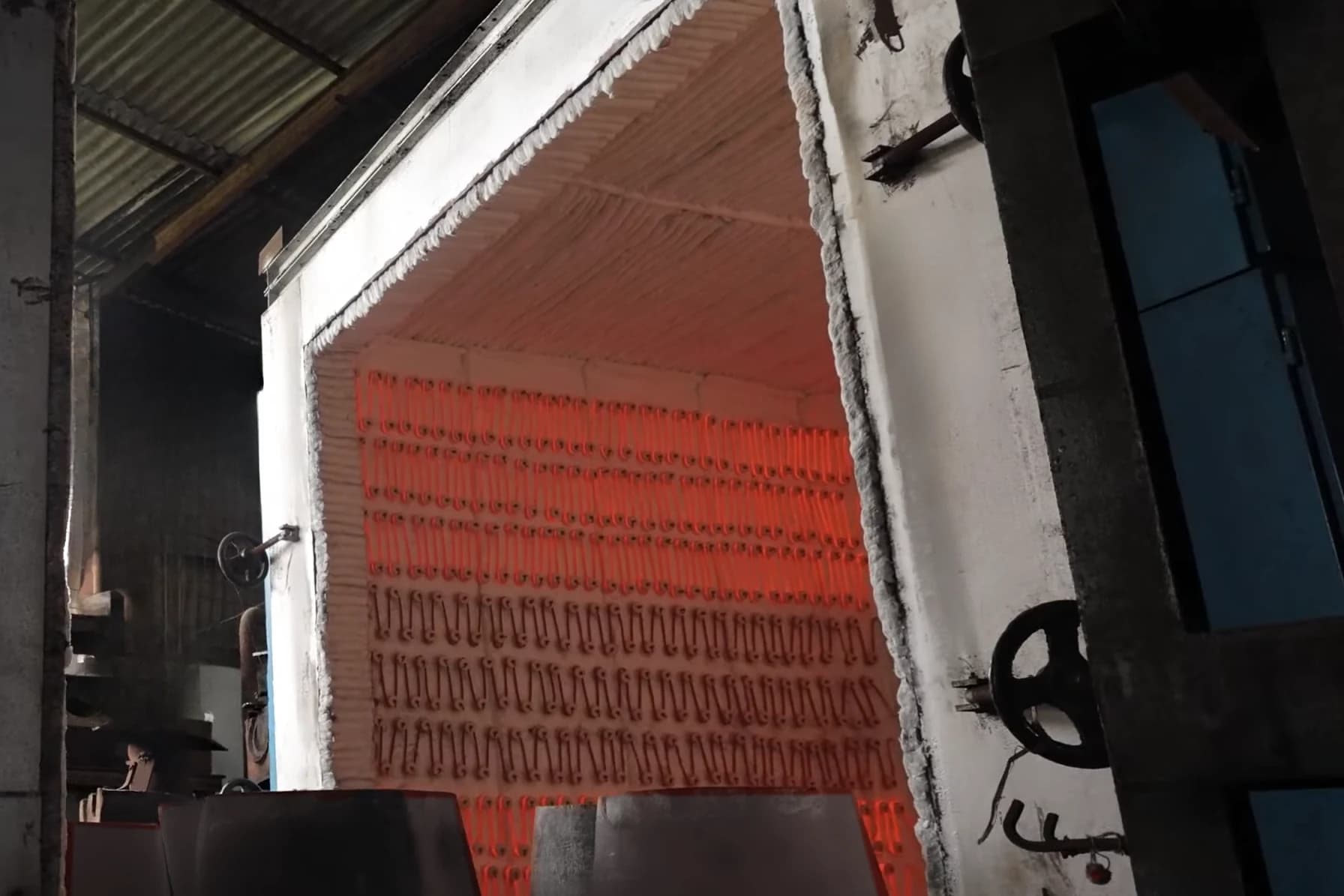
Fig. 06.1 — Heat treatment furnace HF2, door open Electric furnace
Station 6 of 13: Heat treatment
Fittings are heat-treated in our electric furnace, 2500 × 2500 × 2000 mm with a 0–1200 °C range, logged by K-type thermocouples and a strip chart recorder.
OutHeat-treated fittings
2500 × 2500 × 2000 mm0–1200 °C- HF2Heat Treatment Furnace-II (2500mm W × 2500mm L × 2000mm H)×1
- Sr. 31Thermocouples (K-type)×1
- Sr. 32Strip Chart Temperature Recorder (Data Logger)×1
- Sr. 33–35Temperature Indicator (K-type)×3
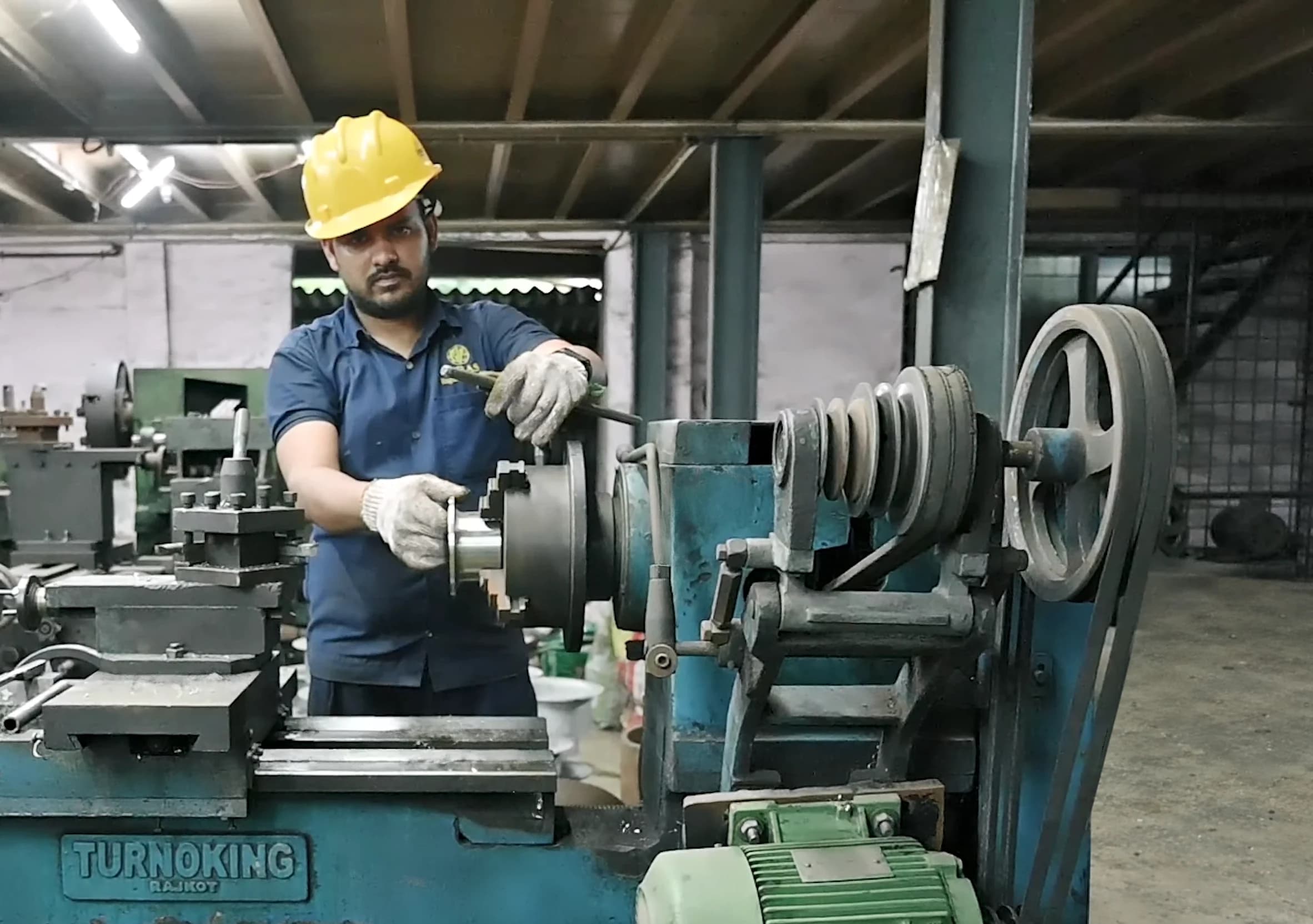
Fig. 07.1 — Lathe and its operator, stainless elbows behind Weld-ready ends
Station 7 of 13: Machining & bevelling
Weld ends are bevelled on our bevel-end machines, ½″ to 24″, and fittings are turned on lathes from 6″ to 28″ centre height.
OutMachined, bevelled ends
Bevel ends ½″ → 24″Lathes 6″ → 28″ centre height- B1–B2Bevel End / Planing Machine (½″ – 24″)×2
- SB1Single Beveling Machine (1500 × 800 × 140mm)×1
- L1–L5Lathe Machine — 6″ to 28″ Centre Height×5
- DM1Drill Machine — Ø 31mm×1
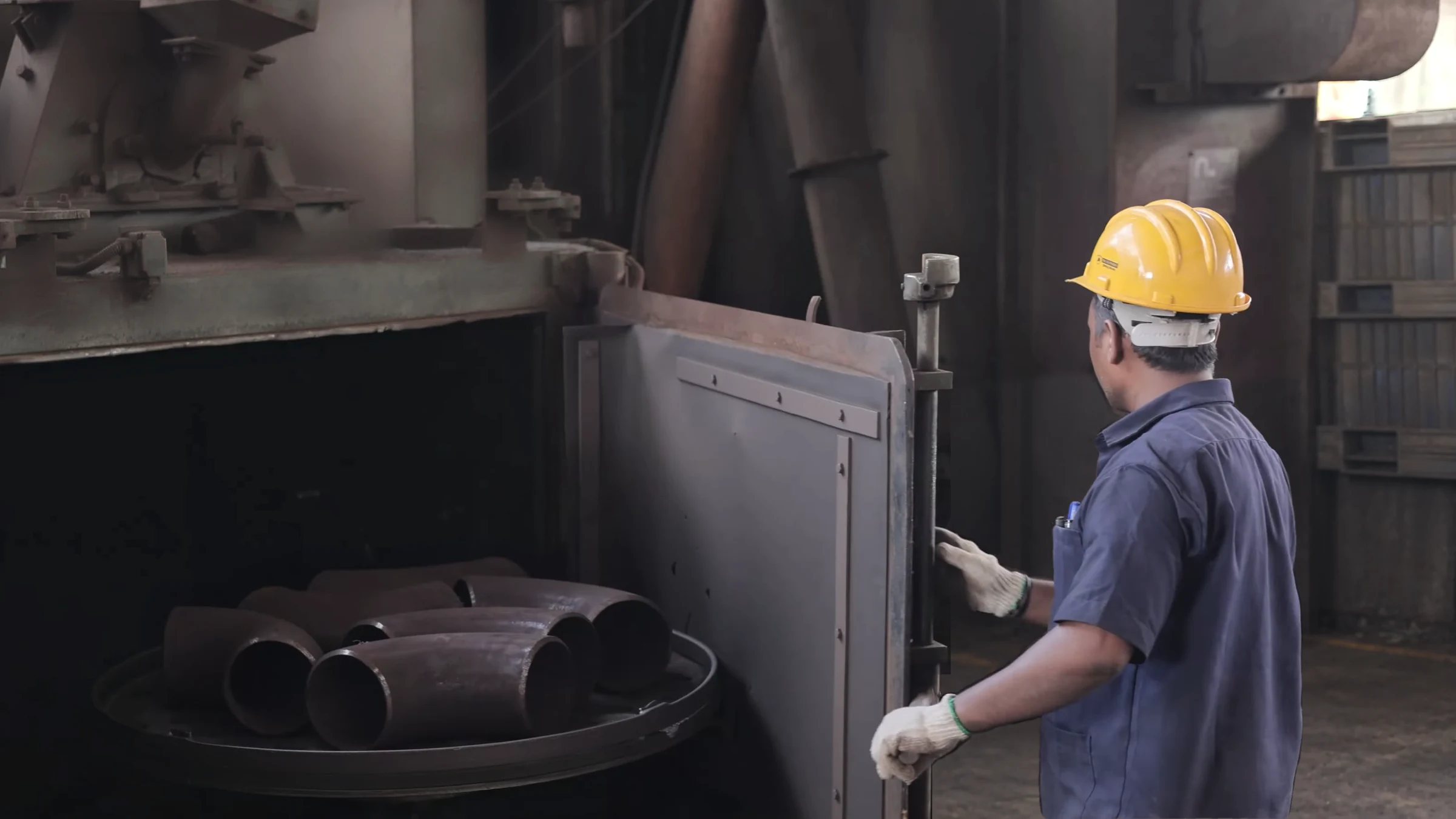
Fig. 08.1 — Shot blasting machine SBM1, loaded with elbows 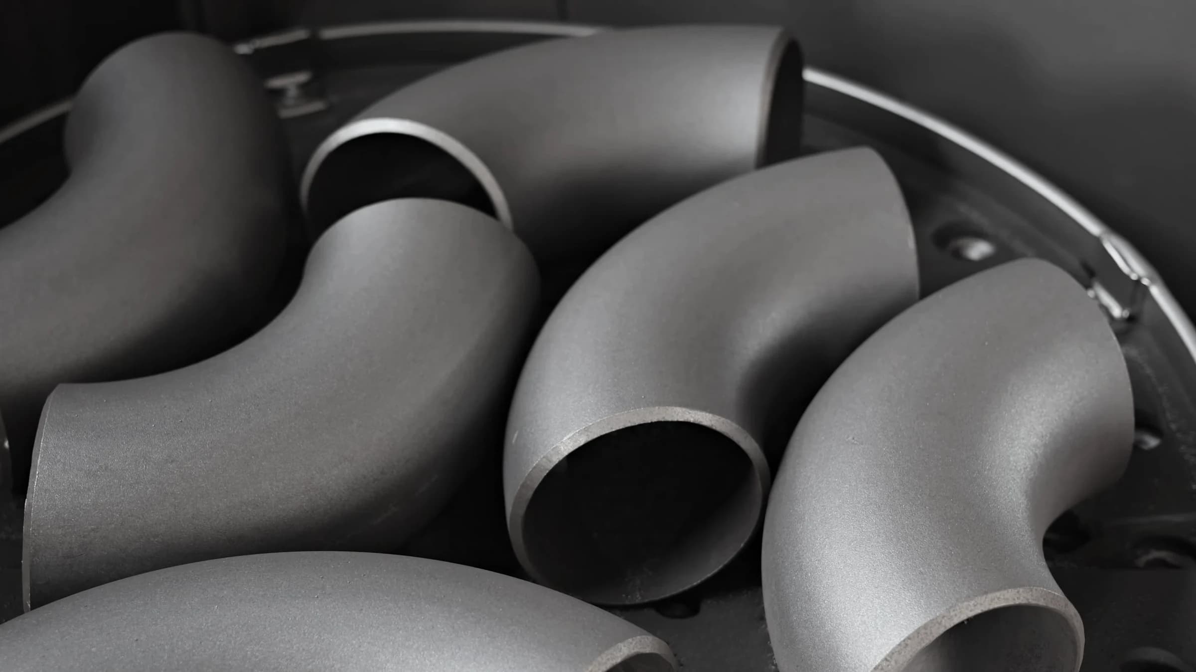
Surface finish
Station 8 of 13: Shot blasting
Formed fittings are loaded onto the turntable of our shot blasting machine and come out with an even, matte surface.
OutEven, matte surface
- SBM1Shot Blasting Machine & Spares×1
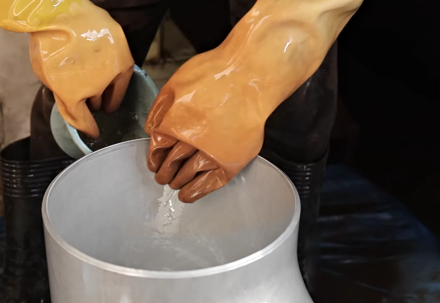
Fig. 09.1 — Rinsing a stainless tee after pickling Stainless steel
Station 9 of 13: Pickling & passivation
Stainless fittings are pickled and passivated by hand, then rinsed with water. The team works in safety helmets, respirators, long rubber gauntlets and gumboots.
OutPickled, passivated stainless
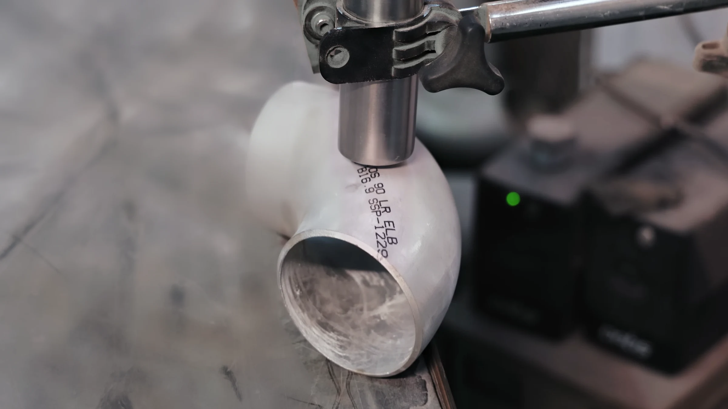
Fig. 10.1 — Column-mounted marking machine over a stainless elbow 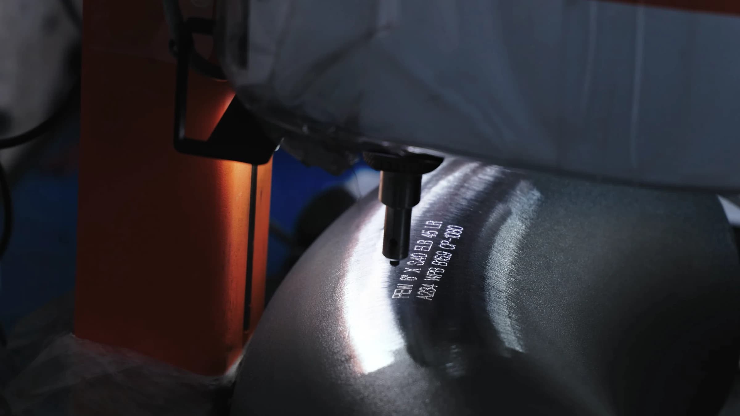
Traceability
Station 10 of 13: Marking
Fittings are dot-peen marked on our column-mounted marking machines with maker, size, schedule, type, material grade and standard.
OutMarked fittings
- CM1–CM5Column Mounted Marking Machine×5
- CM6–CM7Portable Marking Machine×2
- SM1–SM2Fully Automatic Inkjet Printer×2
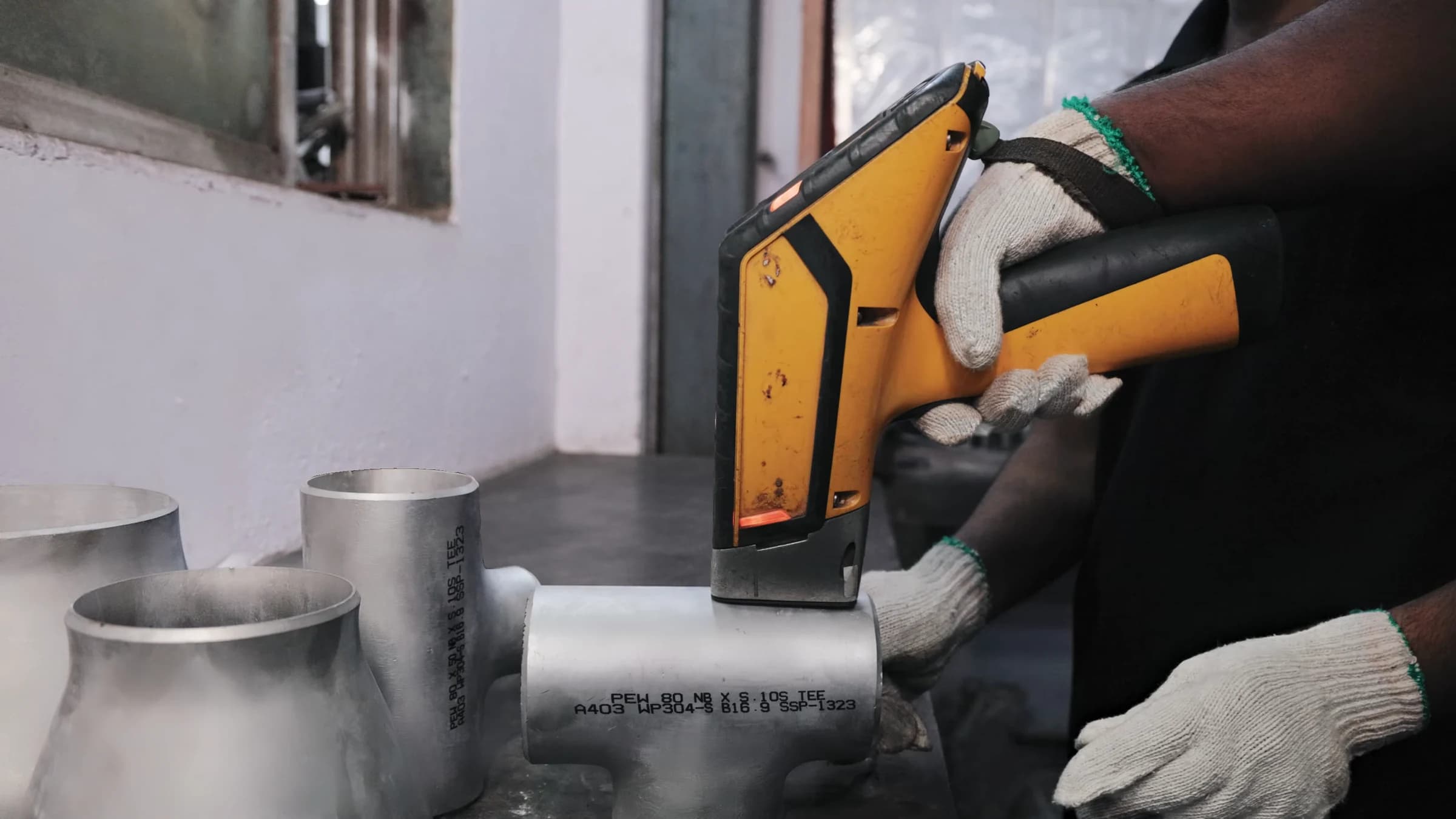
Fig. 11.1 — PMI analyser on a marked stainless tee 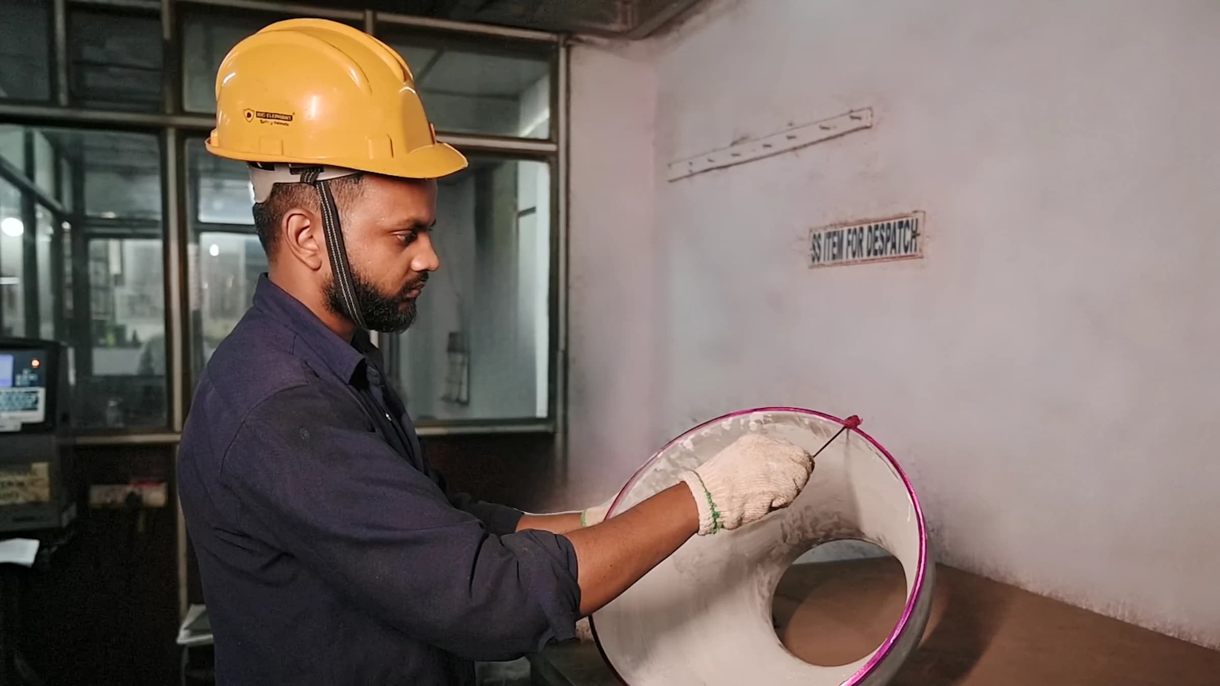
Measured and tested
Station 11 of 13: Final inspection & testing
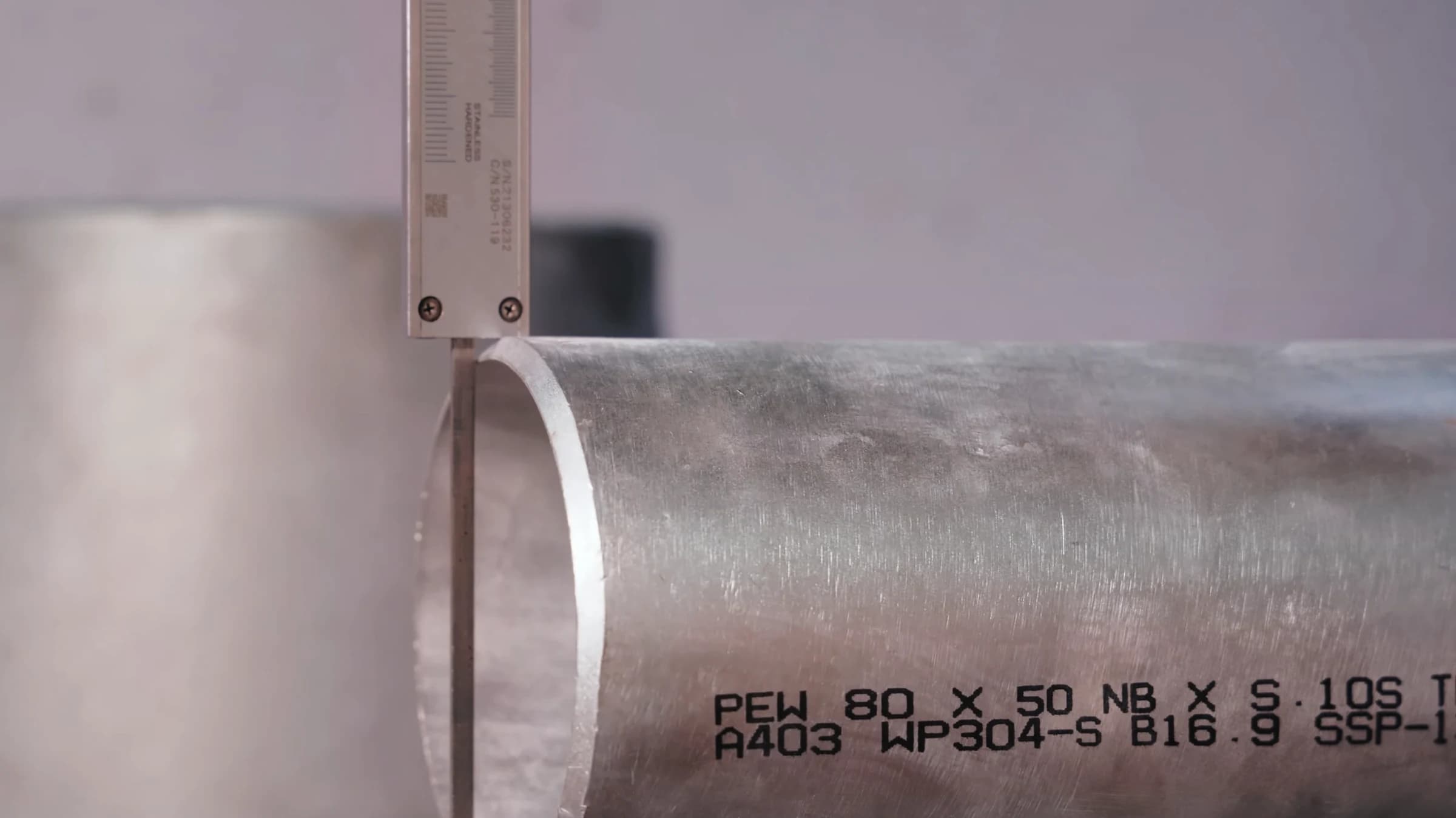
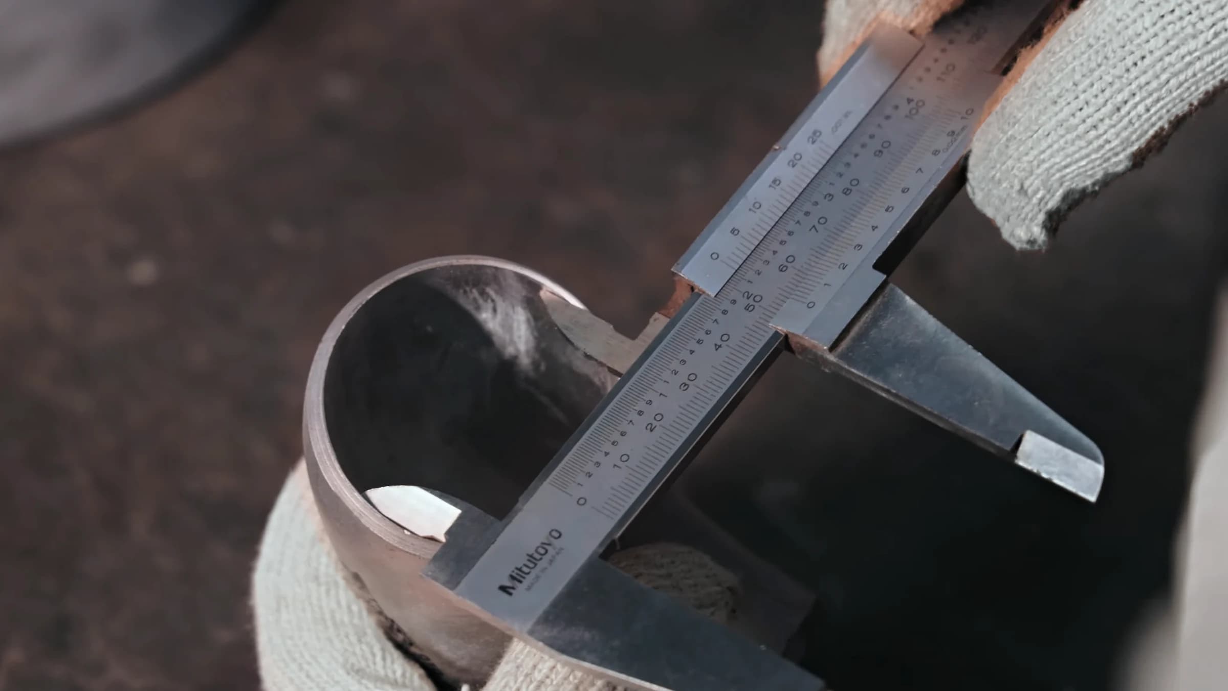
Finished fittings are measured with vernier calipers and checked by PMI analyser for grade, pen tester for hardness, ultrasonic gauge for wall thickness, and by dye-penetrant testing.
OutInspected & tested fittings
- Sr. 20PMI Analyser (Positive Material Identification)×1
- Sr. 24Pen Hardness Tester×1
- Sr. 23Ultrasonic Thickness Gauge (D-Meter)×1
- Sr. 01–10Vernier Caliper (incl. one digital)×10
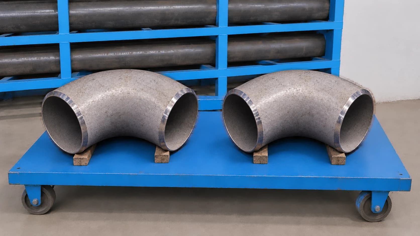
Fig. 12.1 — Finished elbows on a store trolley Ready stock
Station 12 of 13: Finished-goods store
Inspected fittings move to our finished-goods store, kept by type and size until they are packed.
OutStock on the rack
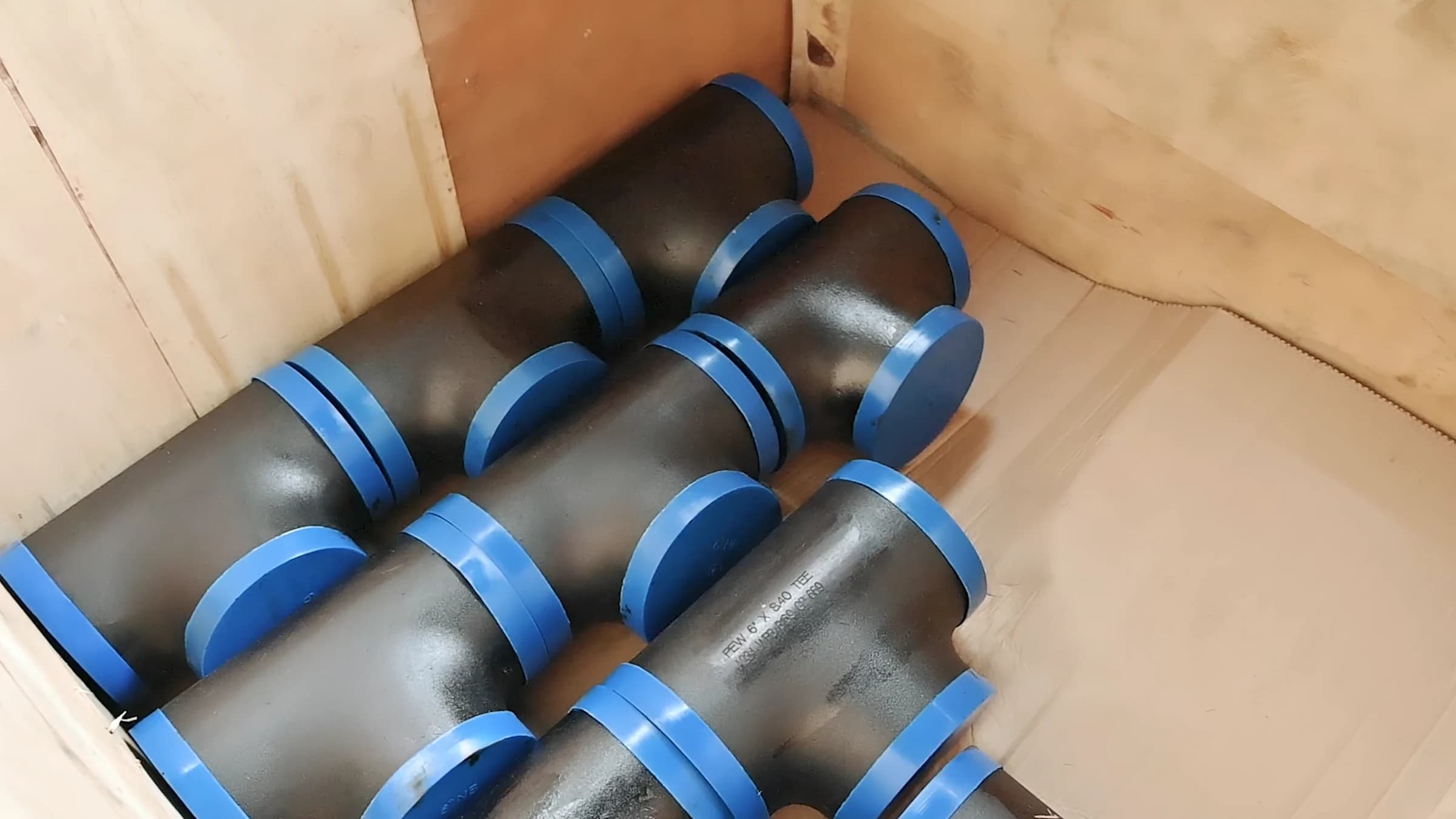
Fig. 13.1 — Capped tees packed in a wooden case Out of the gate
Station 13 of 13: Packing & dispatch
Ends are capped with protectors and fittings are packed into wooden cases for dispatch from our Vasai (E) works.
OutCrated for dispatch
What we form, machine, weld and measure
The headline capacities from our machine list and our List of Calibration. Select one to open its entries in the register below.
08 more capacities
Swipe
71 machines, 74 instruments, one register
Every machine on our shop floor and every entry on our List of Calibration, with its M/C number or, where the list gives one, its ID number. Switch lists or search either.
Spaces optional · try
Category C-02
Forming & Pressing
08/ 71 machines
- Sl. 10
Mandrel Machine (Elbow Range: 4″ × S.40 to 18″ × 20mm thk)
Beijing Make 2014
M/C No.HB1
- Sl. 11
Cold Bending Machine
Cuteral PSM -2018
M/C No.CB1
- Sl. 12
Hydraulic Press — 200 Tons
Self made 2009
M/C No.HP1
- Sl. 13
Hydraulic Press — 250 Tons
Self made 2009
M/C No.HP2
- Sl. 14
Hydraulic Press — 400 Tons
Self made 2009
M/C No.HP3
- Sl. 15
Hydraulic Press — 1000 Tons
Inhouse Machine 2012
M/C No.HP4
- Sl. 16
Hydraulic Press — 1200 Tons
Inhouse Machine 2012
M/C No.HP5
- Sl. 17
Rolling Machine
Self-made 2016
M/C No.RM1
Source: machine list PEW/MNT/L-01 Rev. 11 · 71 machines, each with its M/C number as listed.
[RFQ]Request for quotation
Ready to source precision fittings?
Share your specifications and our team will get back with a detailed quotation — standard ranges or fully customized to your drawings.
Subject · RFQ — Butt weld fittings · Carbon steel
Or write to sales@parasengineeringworks.com